How To Build an FPV Drone (Assembly)
Dive into the exciting world of FPV drones! Follow our step-by-step guide to assemble your own drone. Our detailed step-by-step guide walks you through every part of the process, from connecting the flight controller and motors to installing the camera and receiver.
Building an FPV (First-Person View) drone is an exciting and rewarding project that allows you to dive deep into the world of drones, electronics, and aviation. Whether you're a seasoned enthusiast or a newcomer to the hobby, assembling your own drone provides a hands-on experience that enhances your understanding of how these drones work. In this comprehensive guide, we'll walk you through the step-by-step process of assembling an FPV drone.
We'll be using the following parts for this build:
- FC & ESC Stack: SpeedyBee F405 Mini BLS 35A 20x20 Stack - AliExpress Price 50.68USD
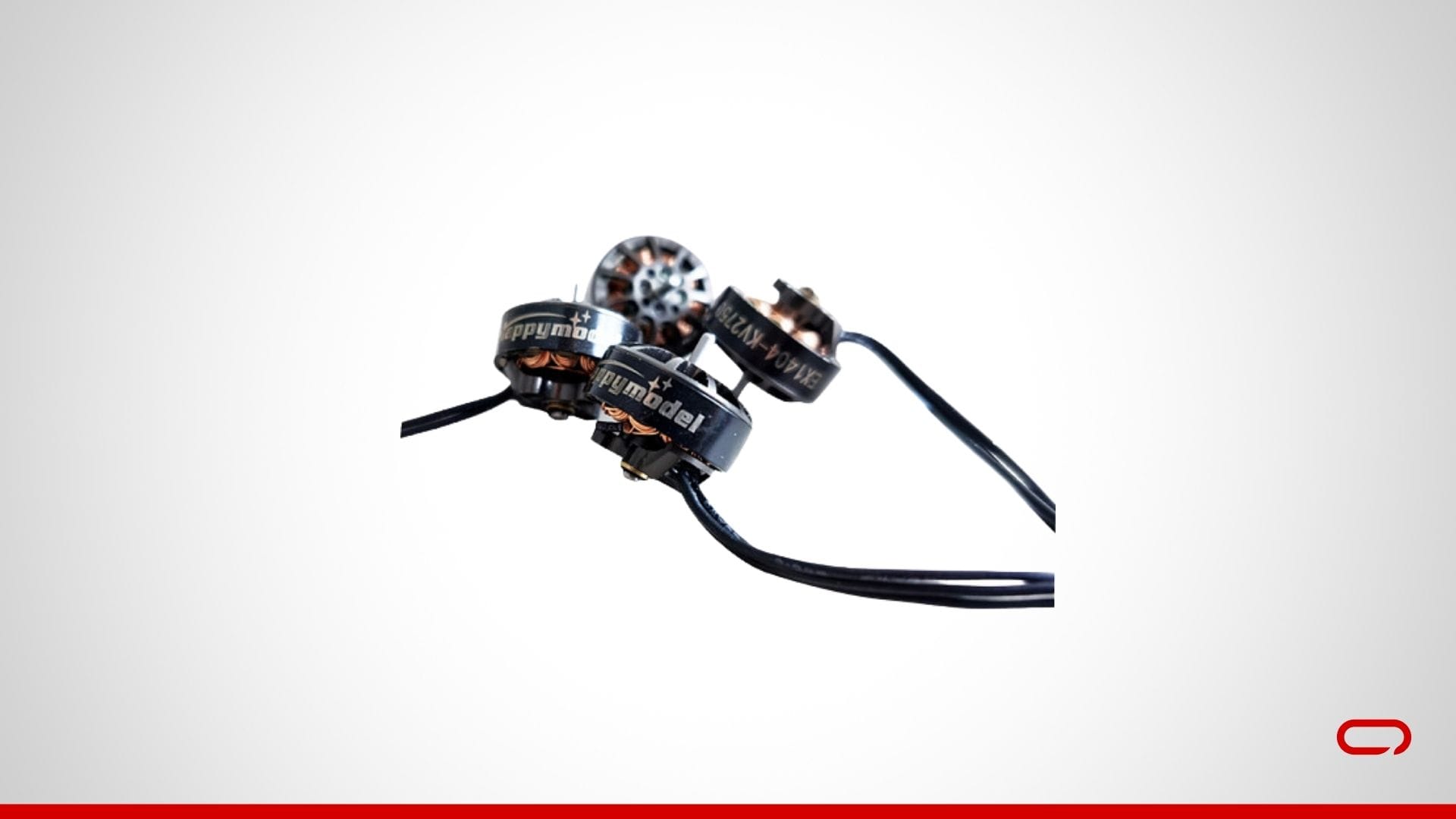
- Motor: Happymodel EX1404 1404 4PCS 3500KV - AliExpress Price: 29.99USD
- VTX: RUSH TINY TANK Nano VTX 48CH 350mW Transmitter 5V Input w/ LED Expansion Board - AliExpress Price: 29.75USD
- Propellers: Emax 3.5 Inch Propeller - AliExpress Pirce: 2.49 USD
- Camera: RunCam Nano 2 FPV Camera 2.1mm Lens - AliExpress Price: 10.99 USD
- Receiver: SpeedyBee Nano 2.4G ExpressLRS ELRS Receiver - AliExpress Price: 6.96 USD
- Frame: HappyModel Crux35 3.5 Inch Frame - AliExpress Price 15.29 USD
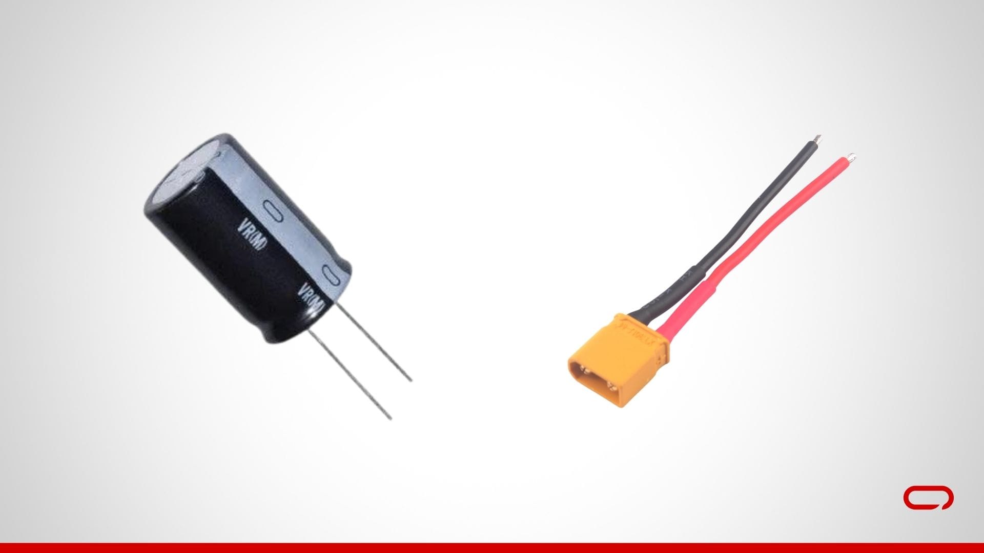
- Smoke Stopper - AliExpress Price 2.38 USD
Tools You Will Need
- Soldering iron and solder
- Hex keys (M2) and screwdrivers
- Electrical tape or heat shrink tubing
- Zip ties
- Tweezers
- Double-sided tape or foam pads
Step 1: Preparing the Flight Controller (FC) and ESC Stack
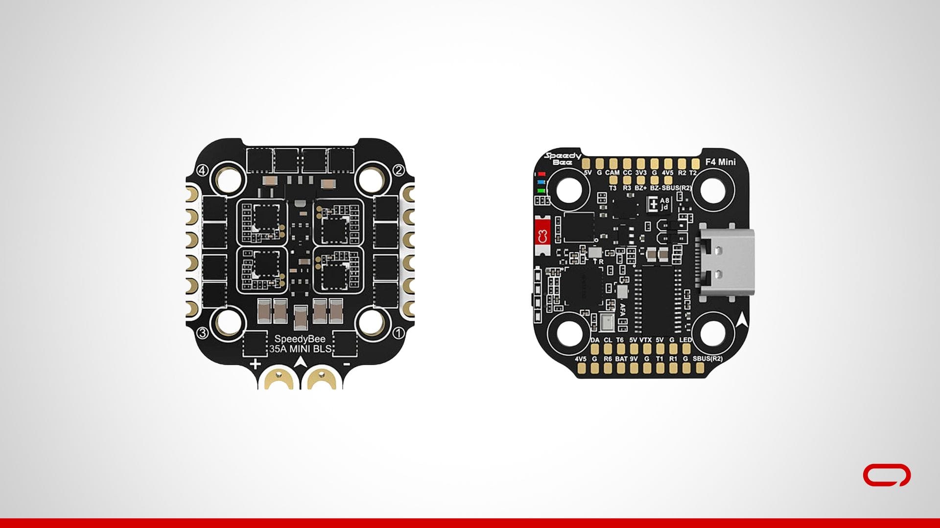
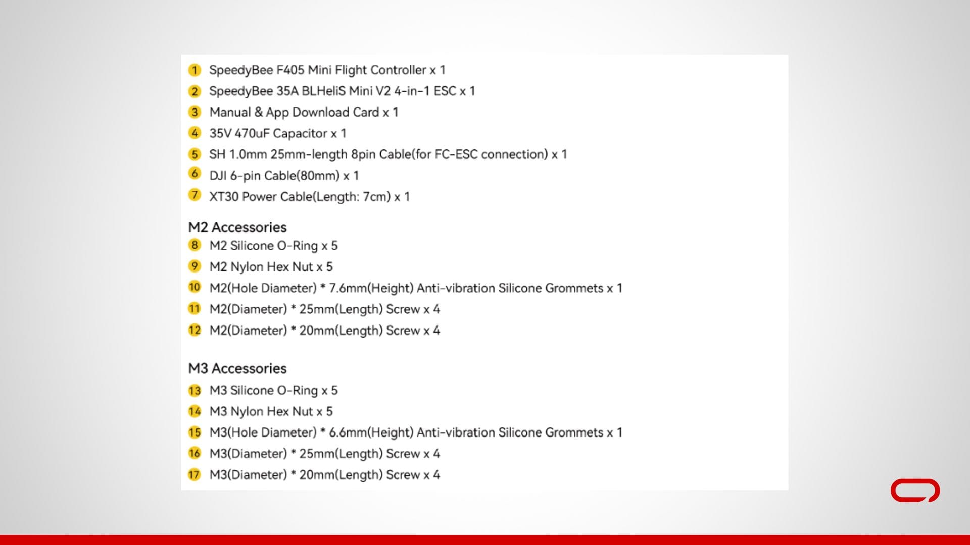
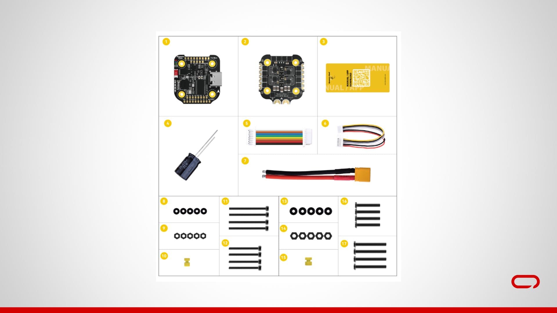
- Unbox the Stack: Start by unboxing the SpeedyBee F405 Mini BLS 35A 20x20 Stack. Lay out all the components to ensure you have everything you need.
- Prepare the FC: Place the FC on a non-conductive surface. Ensure you have a clear view of all the pads.
Step 2: Installing the FPV Camera
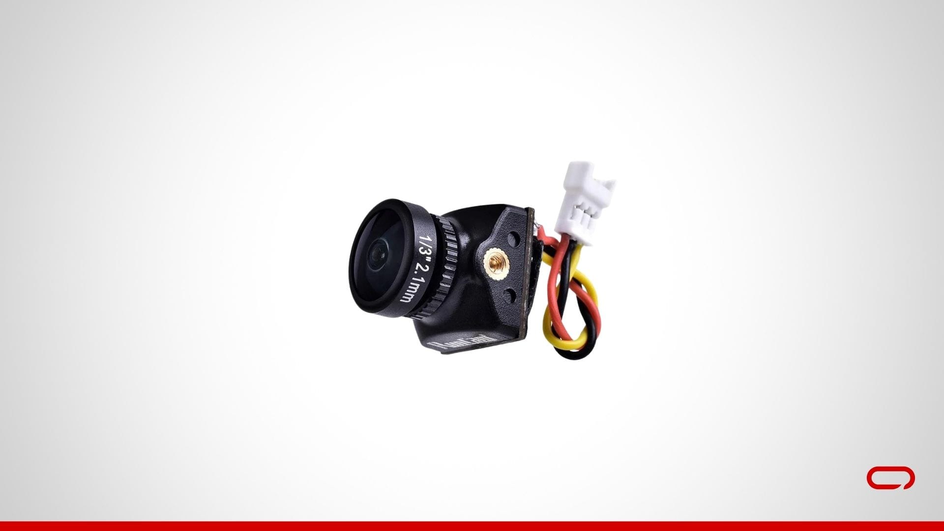
- Connect the Camera Wires: The RunCam Nano 2 FPV Camera typically has three wires:
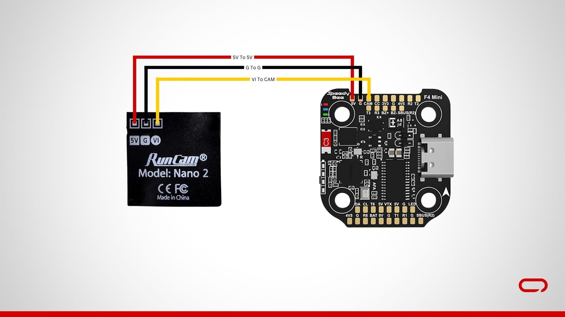
- Power 5V (red): Solder to a 5V pad on the flight controller.
- Ground (black): Solder to a GND pad on the flight controller.
- Video (yellow): Solder to the CAM pad on the flight controller.
Step 3: Installing the VTX
Connect the VTX Wires: The RUSH TINY TANK Nano VTX typically has several wires:
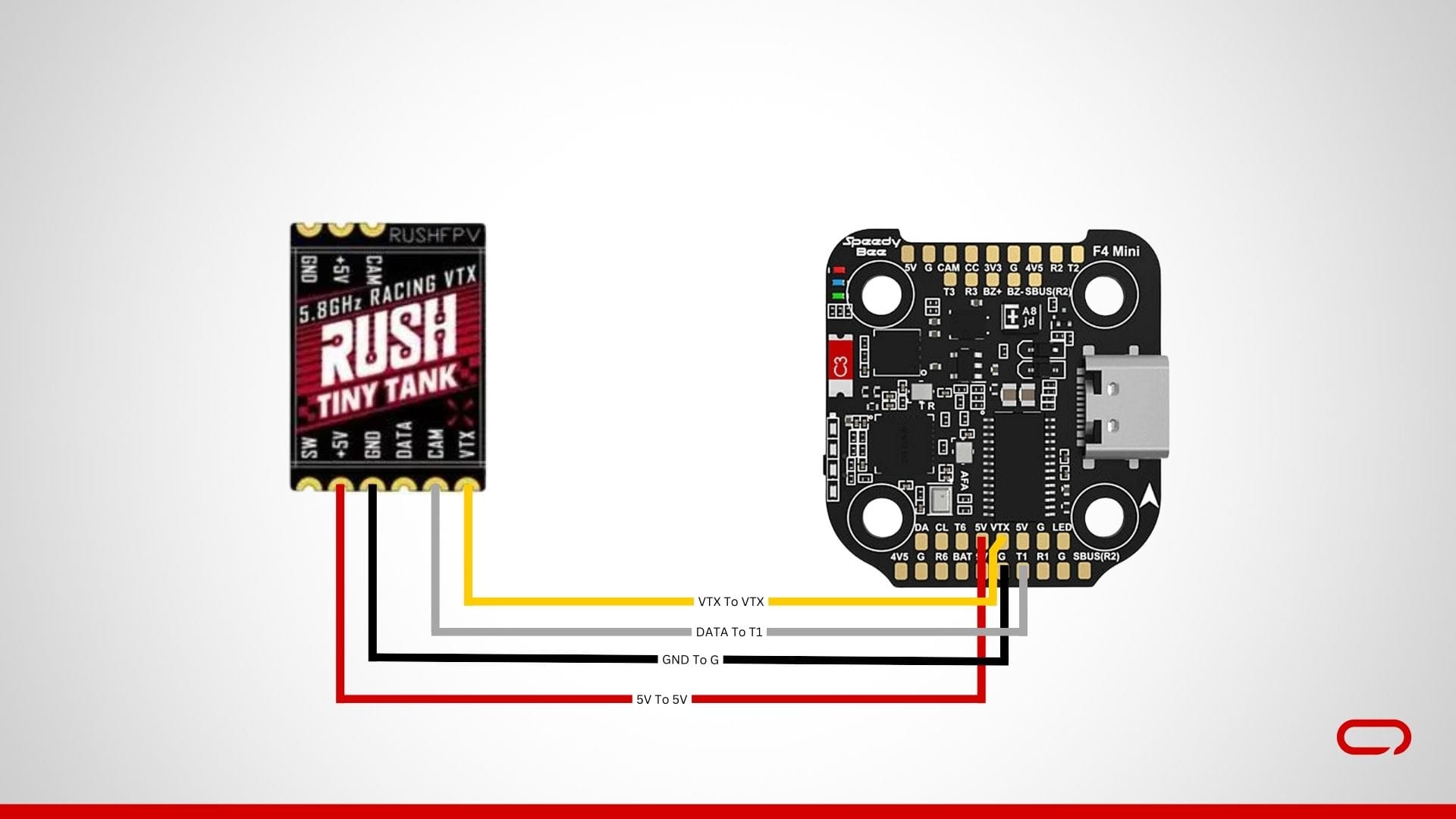
- Power 5V (red): Solder to a 5V pad on the flight controller.
- Ground (black): Solder to a GND pad on the flight controller.
- VTX (yellow): Solder to the VTX pad on the flight controller.
- Data - SmartAudio (white): Solder to the T1 pad on a UART port on the flight controller for VTX control.
Step 4: Installing the Receiver
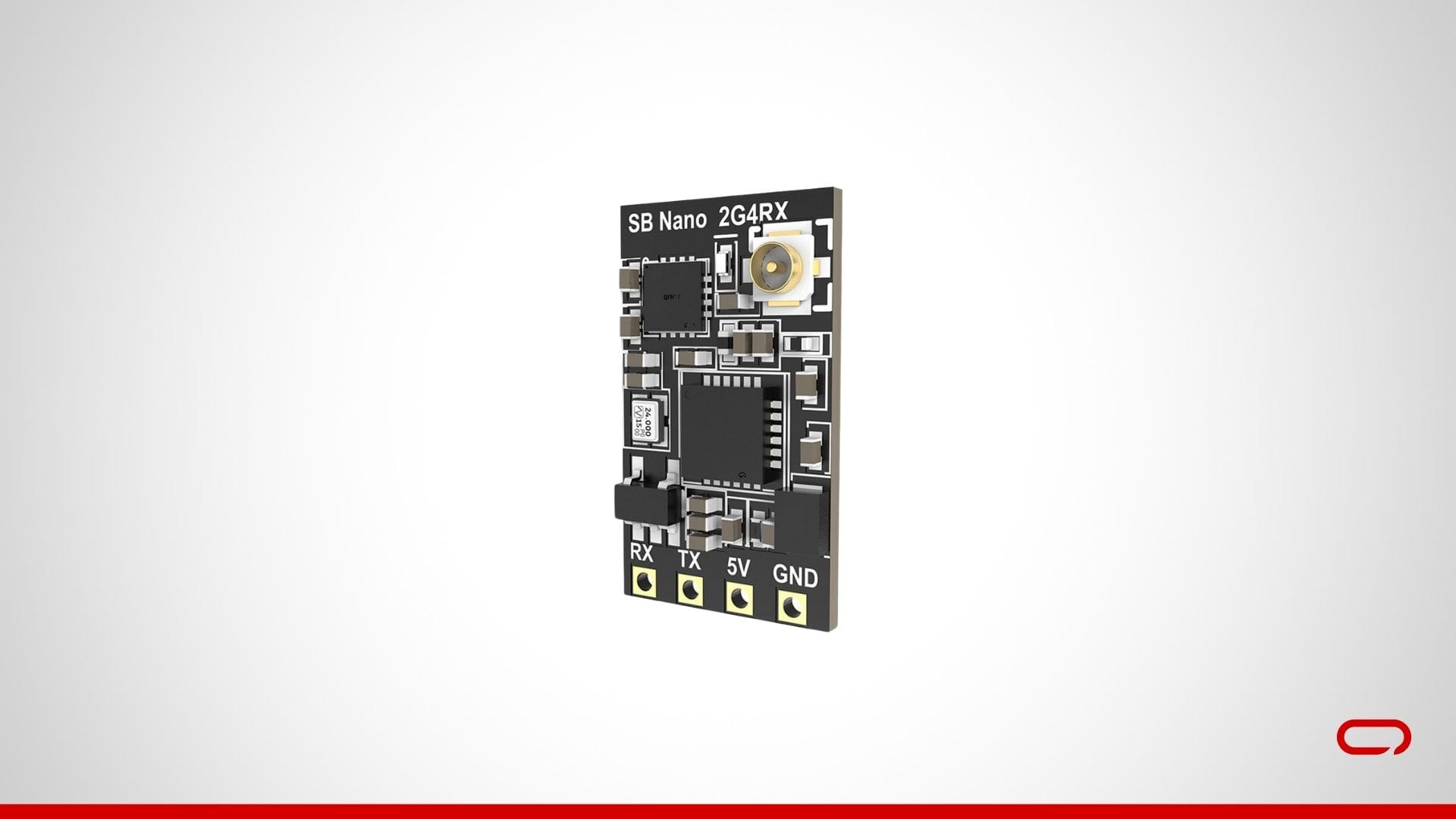
Connect the Receiver Wires: The SpeedyBee Nano 2.4G ExpressLRS ELRS Receiver will have several wires:
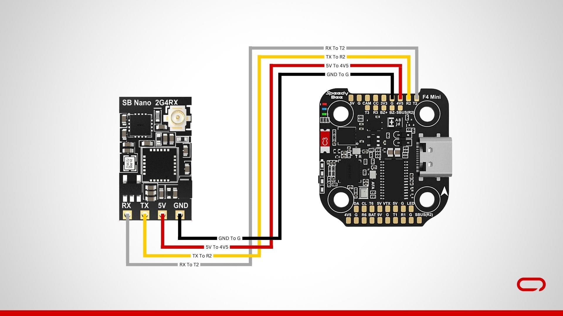
- Power 5V (red): Solder to a 5V pad on the flight controller.
- Ground (black): Solder to a GND pad on the flight controller.
- TX (yellow): Solder to the R2 pad on a UART port on the flight controller (typically UART2).
- RX (white): Solder to the T2 pad on a UART port on the flight controller (typically UART2).
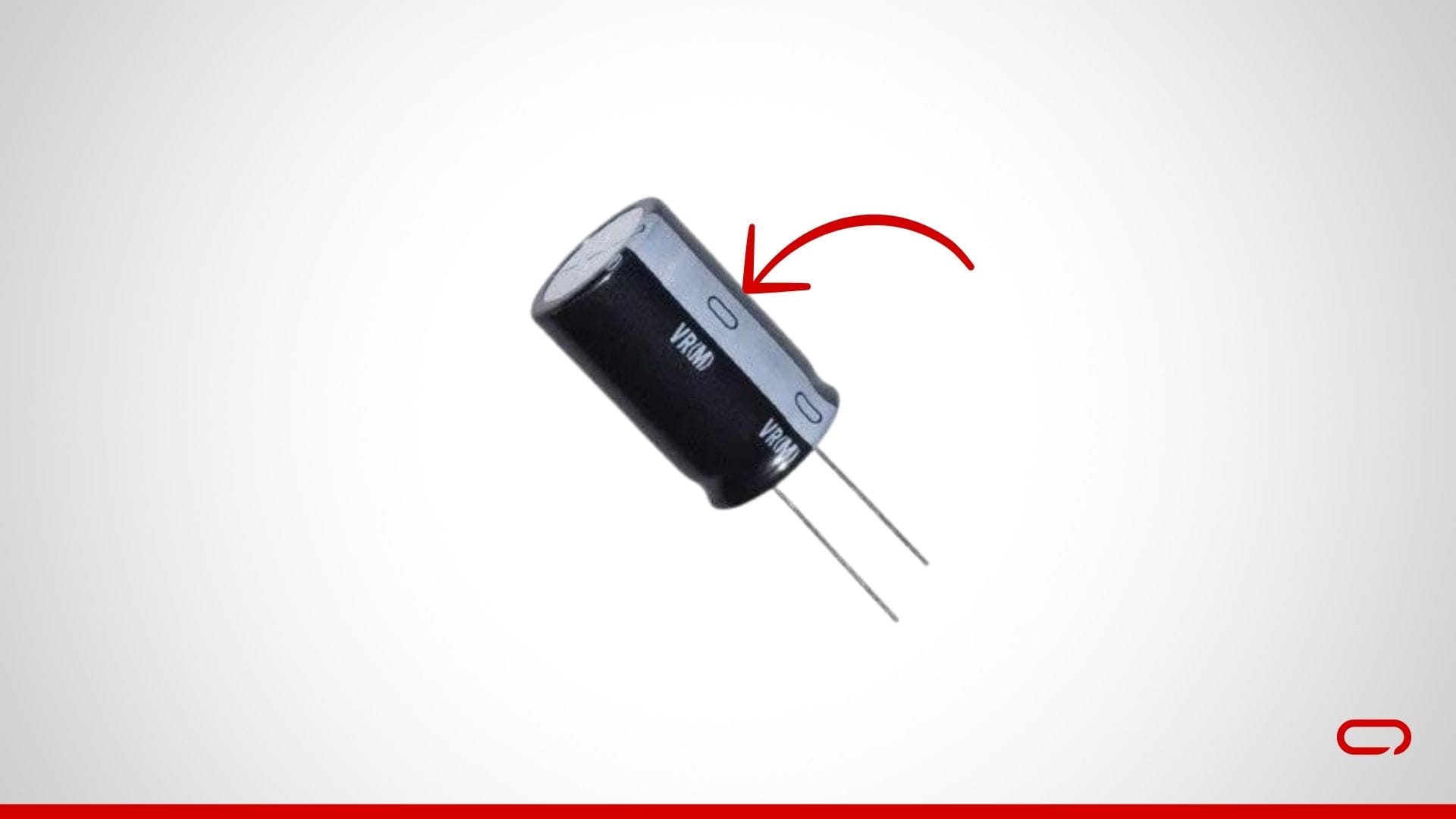
Step 5: Soldering the Battery Leads and Capacitor
Prepare the ESC: Place the ESC on a non-conductive surface. Ensure you have a clear view of all the pads.
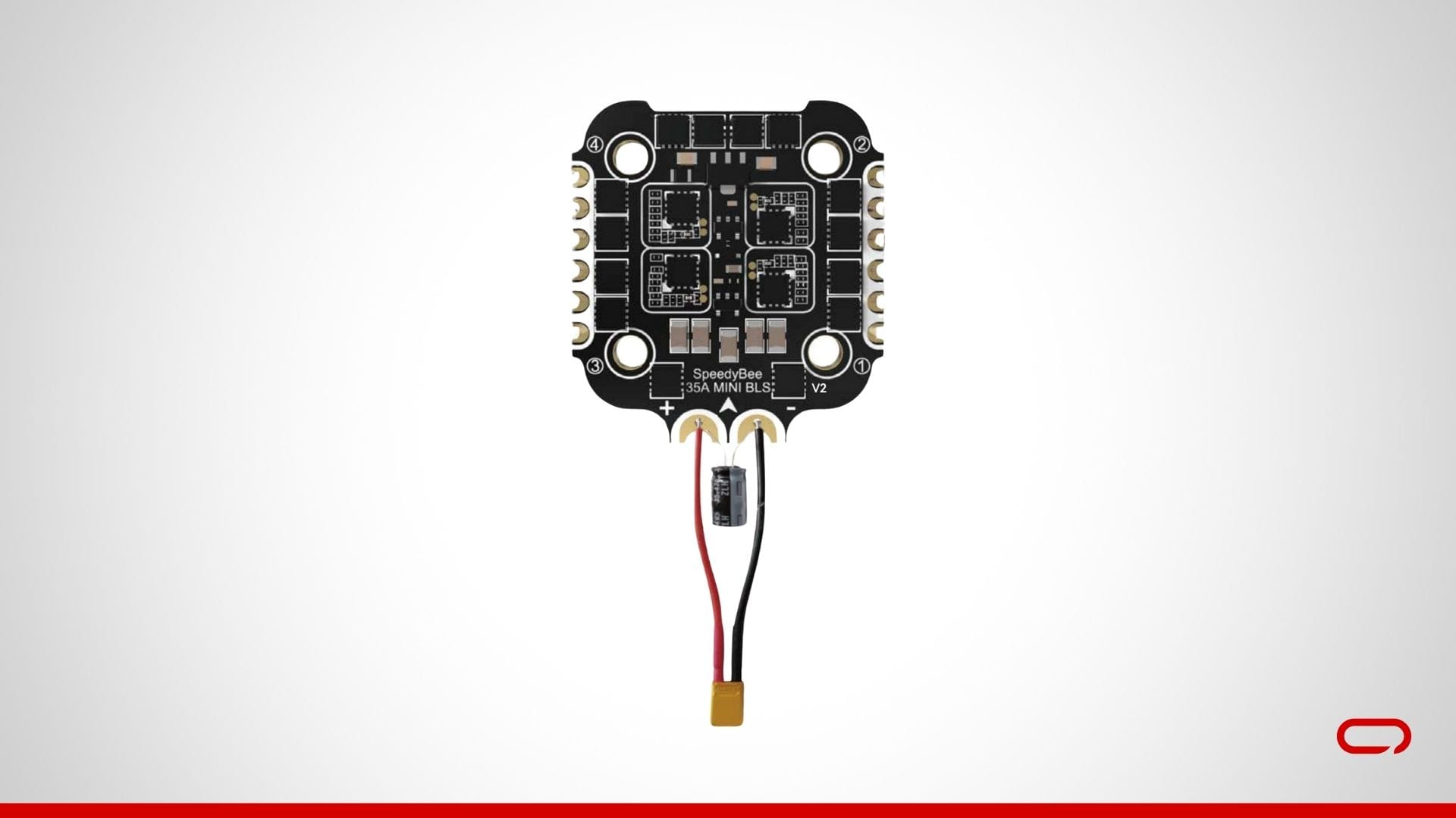
- Install the Capacitor: Install the capacitor through the holes across the + and - pads to help filter out voltage spikes and noise.
- Solder the Battery Leads: Solder the battery leads to the ESC pads. This involves connecting the positive wire (red) to the + pad and the negative wire (black) to the - pad. Use a higher temperature and a good amount of solder to ensure a strong connection.
Step 6: Soldering the Motors to the ESC
Connect the Motors to the ESC: Solder the motor wires to the ESC pads on the flight controller board. Each motor will have three wires that need to be connected to the corresponding pads on the ESC:
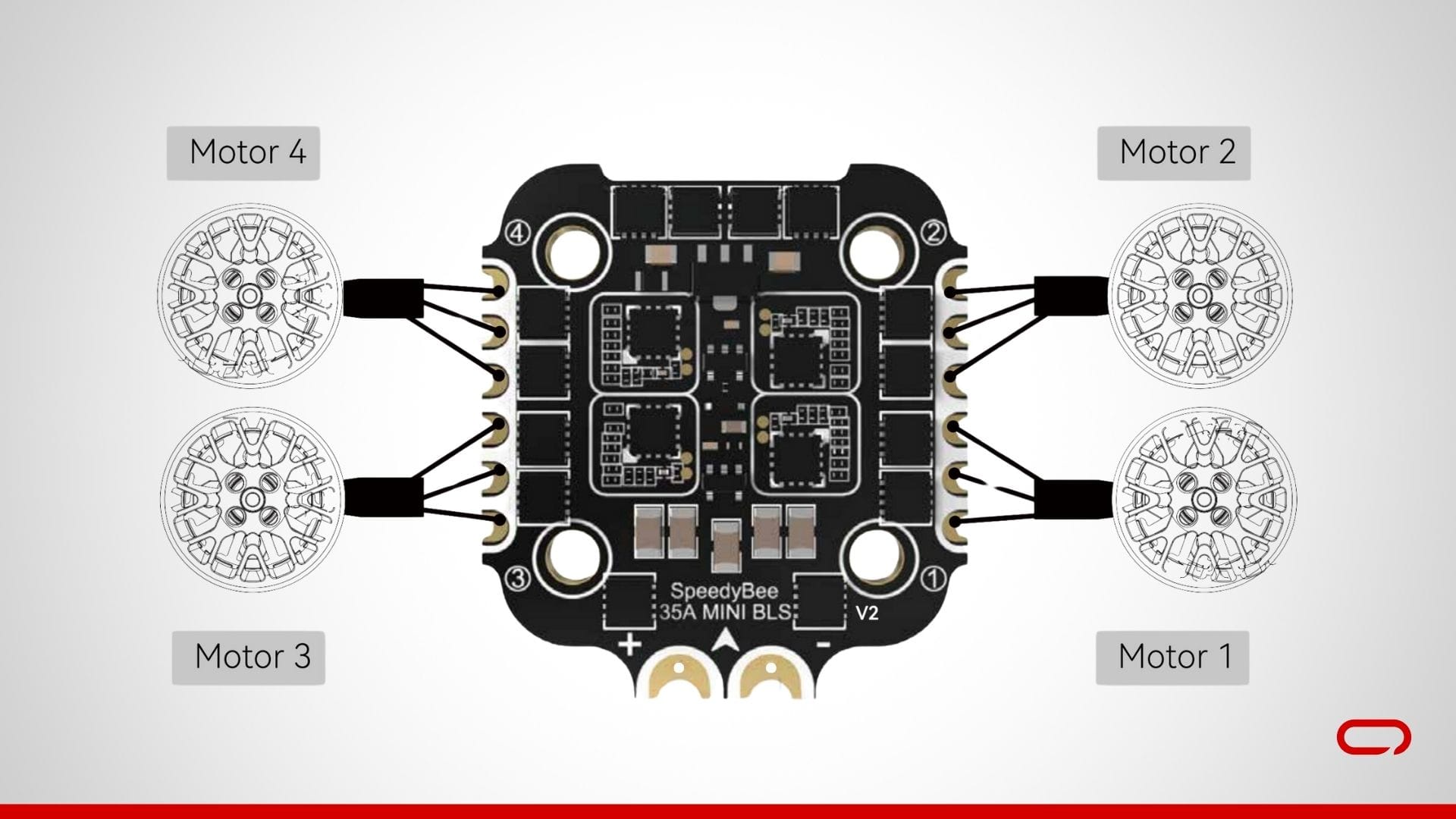
- Motor 1: Connect to M1 pads.
- Motor 2: Connect to M2 pads.
- Motor 3: Connect to M3 pads.
- Motor 4: Connect to M4 pads.
Step 7: Assembling Components to the Frame
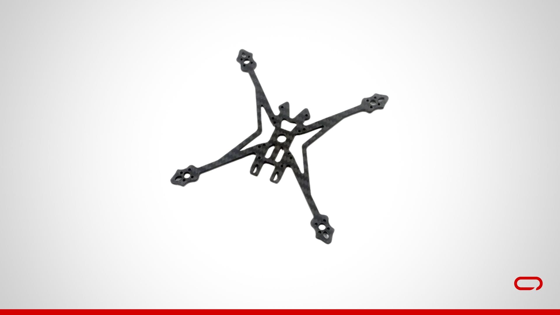
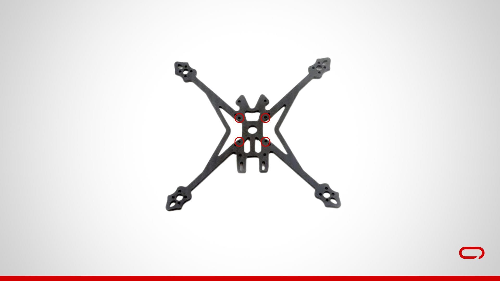
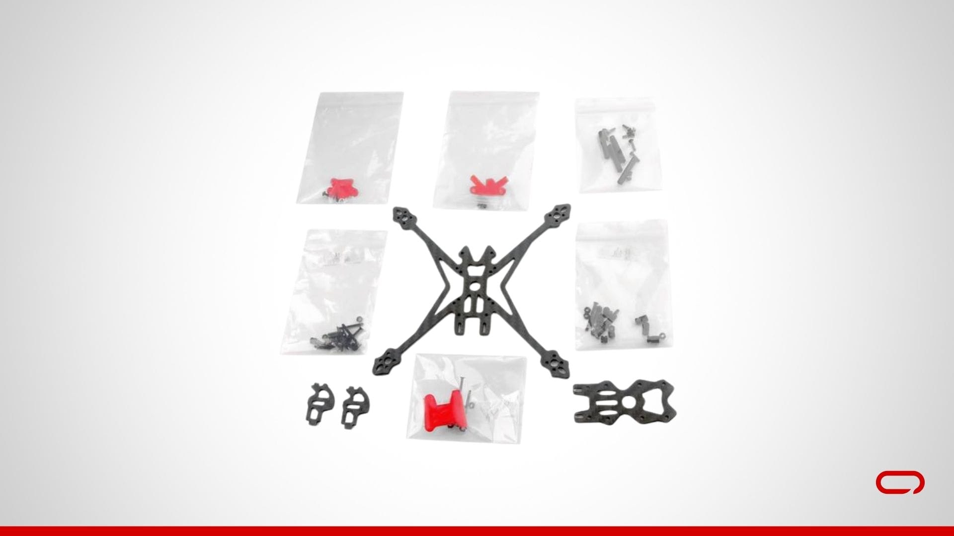
- Unbox the Frame: Start by unboxing the HappyModel Crux35 3.5 Inch Frame. Lay out all the components to ensure you have everything you need. First, run the battery strap through the backplate.
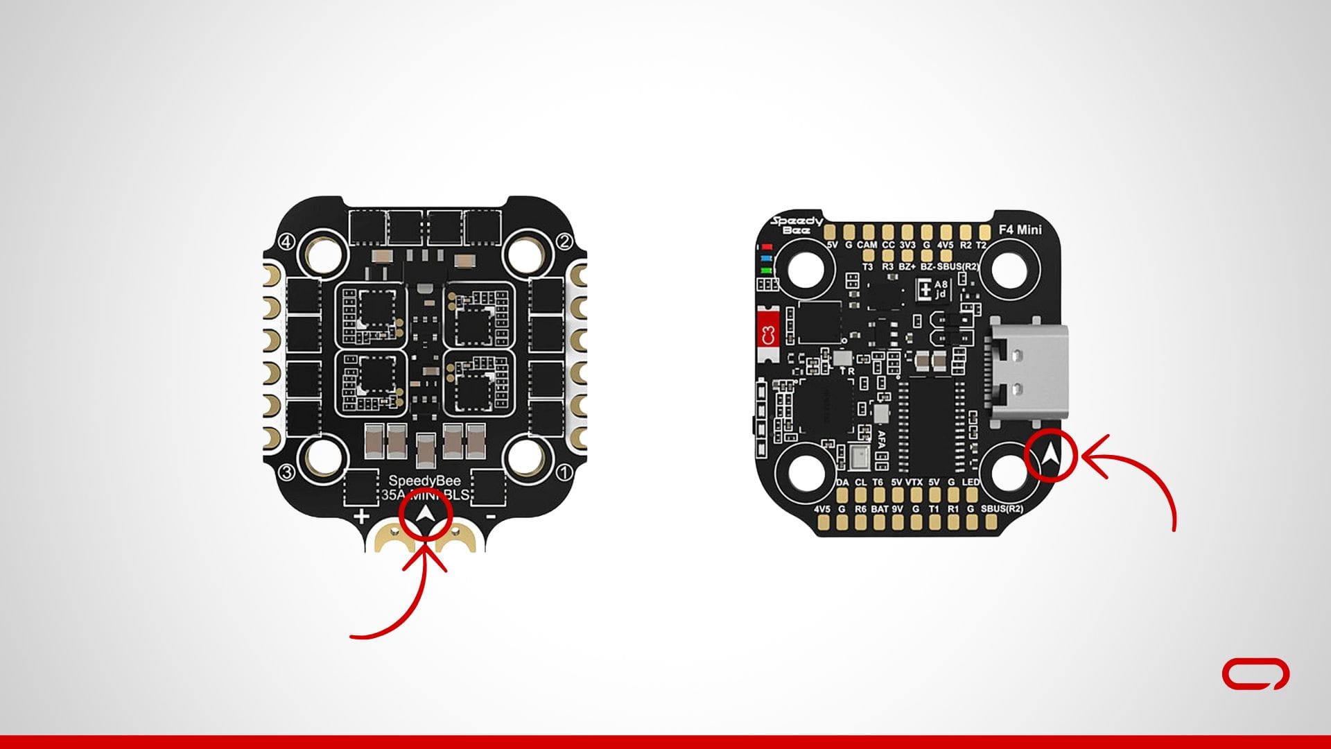
- Install the ESC: Use the M2 screws provided, ensuring they are of the appropriate length. Place the ESC in the center of the frame and run the M2 screws through the holes in the center of the frame. Ensure the arrow on both the FC and ESC is facing up and forward, towards the camera. This orientation is crucial for proper functioning.
- Add the Flight Controller (FC): Position the FC on top of the ESC, aligning the mounting holes. Secure the FC with the provided nuts. Tighten the nuts so they are snug but not overly tight. Ensure the arrow on both the FC and ESC is facing up and forward, towards the camera. This orientation is crucial for proper functioning.
- Mount the Motors: Attach the Happymodel EX1404 motors to the designated motor mounts on the frame using the provided screws. Ensure that the motors are securely fastened.
- Install the FPV Camera: Take the camera bracket and use the M2 screws provided to mount the camera securely in the bracket. Attach the bracket to the designated spot on the frame at the front.
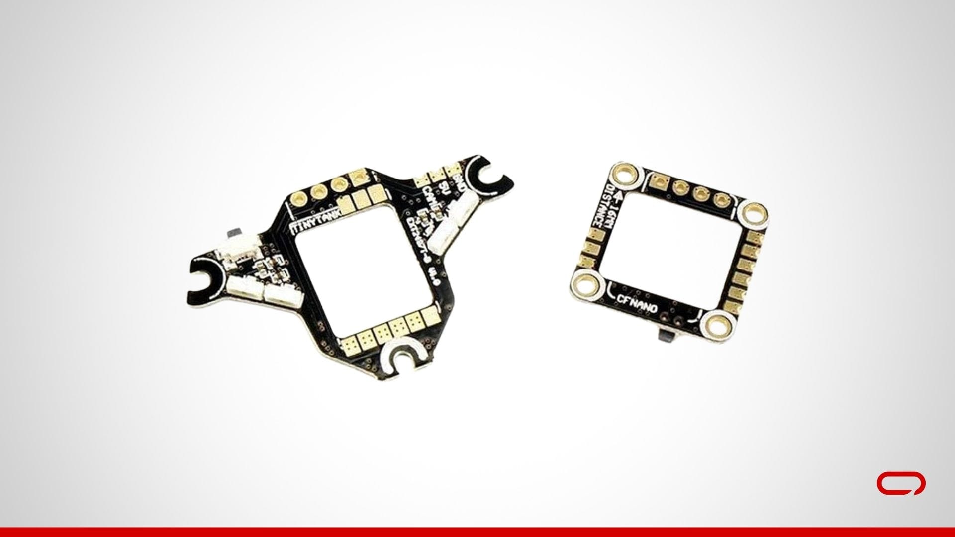
- Install the VTX: The VTX can be mounted on the top plate of the frame. Use M2 screws, zip ties, or double-sided tape to secure the VTX in place.
- Install the Receiver: Mount the receiver at the back of the drone. Use zip ties or double-sided tape to secure the receiver. Slip the antenna through the TPU part vertically for optimal signal reception.
Step 8: Assembling the Frame
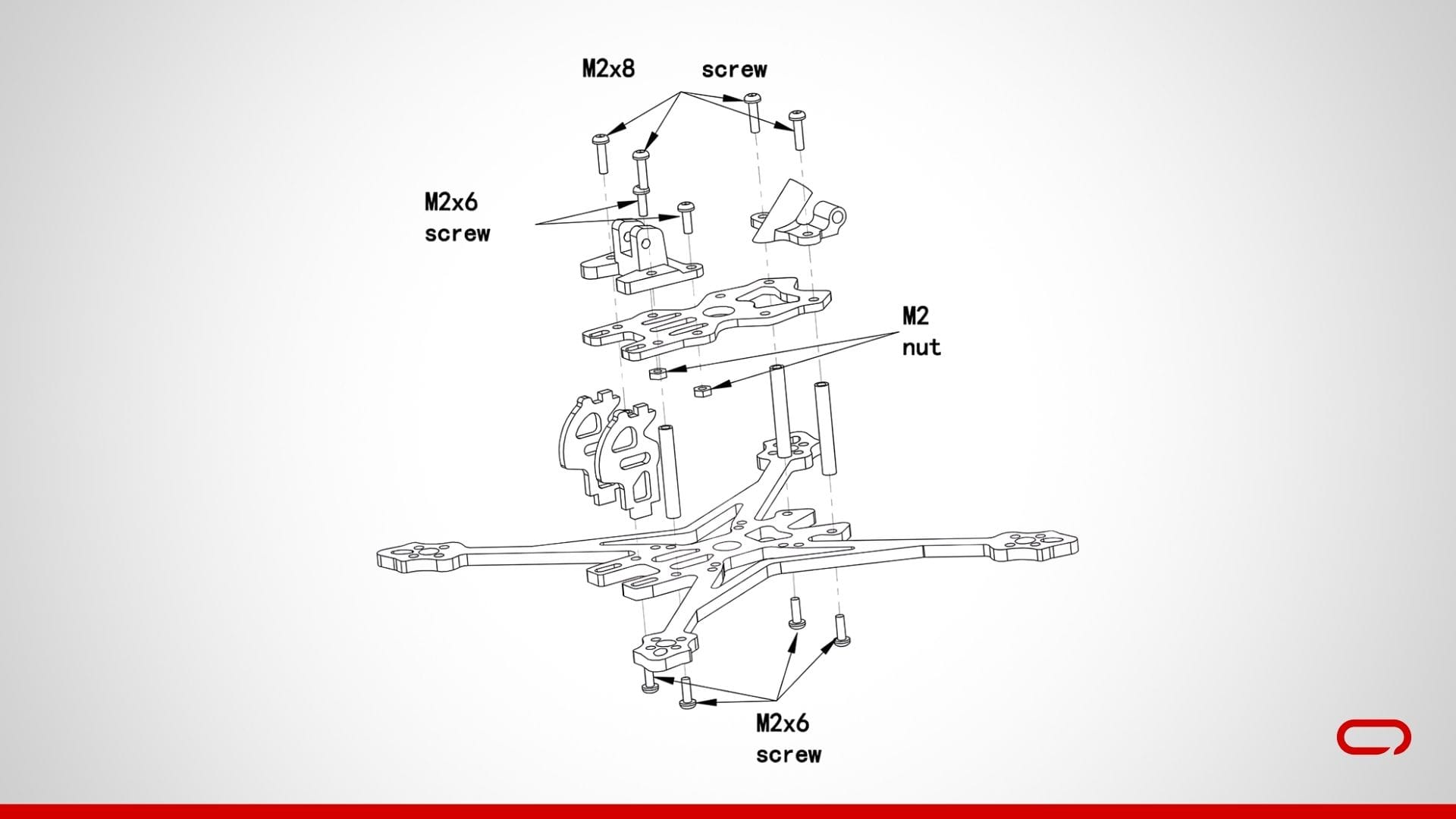
- Add the Spacers: Insert the spacers into the designated slots on the frame. Secure the spacers with the provided M2x6 screws.
- Attach the TPU Parts: Position the TPU parts in their designated locations on the top plate. Secure the TPU parts using the M2x6 screws and the M2 nuts provided.
- Install the Top Plate: Place the top plate on the spacers. Use the M2x8 screws provided to secure the top plate to the spacers, ensuring it is tightly fitted.
- Install the Battery Pad: Apply the battery pad sticker at the bottom of the drone.
Step 9: Bench Testing
- Initial Power Check: Connect the battery and power up your drone using the smoke stopper without propellers. Ensure that all components power on correctly.
- Check Motor Direction: Use Betaflight to check the motor directions. Ensure that each motor spins in the correct direction. If a motor is spinning in the wrong direction, you can reverse it in Betaflight.
- Set your UART: In Betaflight, navigate to the Ports tab. Set the peripherals for UART1 to VTX (TBS SmartAudio) and Enable Serial RX for UART2.
- Apply Presets: In the Presets tab of Betaflight, search for "Rush Tiny Tank." Click on it, select "Rush Tiny Tank" from the dropdown list, and then apply the preset. Do the same for ExpressLRS 250Hz or 500Hz, depending on your transmitter (controller) settings.
- Verify Camera and VTX: Ensure that the camera feed is being transmitted correctly and that the VTX is set to the correct channel and power level.
- Receiver Binding: Bind your transmitter (controller) to the SpeedyBee Nano 2.4G ExpressLRS ELRS Receiver according to the manufacturer's instructions. Verify that all controls are working correctly.
Step 10: Propellers and Final Checks
- Attach the Propellers: Secure the propellers to the motors. Ensure that the propellers are oriented correctly according to the motor rotation direction (clockwise or counterclockwise).
- Final Check: Double-check all connections, screws, and settings. Ensure that everything is secure and that there are no loose wires.
Step 11: Test Flight
- Safety Check: Before the first flight, double-check all screws, connections, and settings.
- Power Up: Connect the battery and power up your drone without the smoke stopper. Ensure that all components are working correctly.
- Maiden Flight: Perform a maiden flight in a safe, open area. Start with gentle maneuvers to ensure everything is functioning properly.
Conclusion
Congratulations! You've successfully assembled your FPV drone. Building your own drone can be a complex yet incredibly rewarding experience, providing you with a deeper understanding of how drones work and the satisfaction of flying something you've created yourself. Enjoy your flights and always prioritize safety. Happy flying!
Feel free to reach out in the comments if you have any questions or need further assistance.