DIY Meshtastic - How To Build Your Own Meshtastic Device with FakeTec PCB & NRF52840
This guide details building a low-cost Meshtastic node using an NRF52840 Pro Micro, HT-RA62 LoRa module, and FakeTec PCB. Total cost is around $11. Assembly requires SMC soldering skills, followed by bootloader updates and Meshtastic firmware installation.
Learn how to build your own low-cost Meshtastic node using the FakeTec PCB design, NRF52840 Pro Micro, and an HT-RA62 LoRa module. This compact and efficient build offers the perfect balance between affordability and functionality for your mesh communication needs.
Hardware
Here's what you'll need to get started:
- 1x NRF52840 Pro Micro - $3.59
- 1x HT-RA62 LoRa Module - $4.92
- 5x FakeTec PCB - approximately $2.00 from JLCPCB
- Soldering iron + solder (60/40)
- Tweezers - $3.00 (recommended for SMC work)
- Small wire cutters
- Eye protection
- Electrical tape
Total build cost: ~$11.00 (excluding shipping and any optional components)
PCB Ordering
To order the PCB from JLCPCB:
- Navigate to JLCPCB's quote page
- Download the latest Gerber files (v4) from the FakeTec PCB repository
- Upload the Gerber ZIP file to JLCPCB
- Keep all the default PCB settings (you can change the PCB color if desired)
- Place your order and await delivery
Component Details
NRF52840 Pro Micro
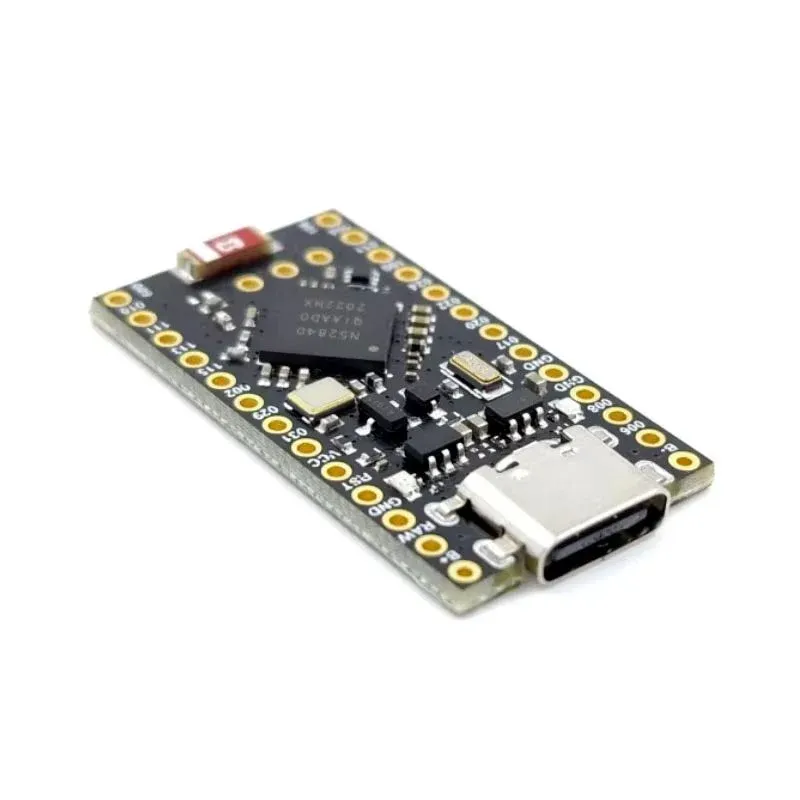
The NRF52840 Pro Micro is an excellent choice for building a Meshtastic LoRa Node. This compact board features:
- Integrated Battery Management System (BMS)
- Bluetooth connectivity
- Very low power consumption
- Small form factor
This allows your node to run on a small battery for days. However, it's important to note that the NRF52840 does not have WiFi capabilities, so features like the PAX counter or connecting to MQTT via WiFi won't be available. This board is best suited for applications that rely on Bluetooth and LoRa communication.
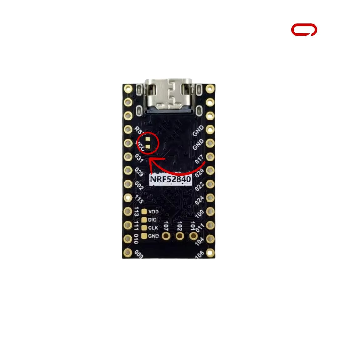
If you plan to use a larger battery, you must short the BOOST pads on the back of the board (located next to RST and VCC).
Battery Charge Current: Without BOOST jumper: 100mA | With BOOST jumper: 300mA
HT-RA62 LoRa Module
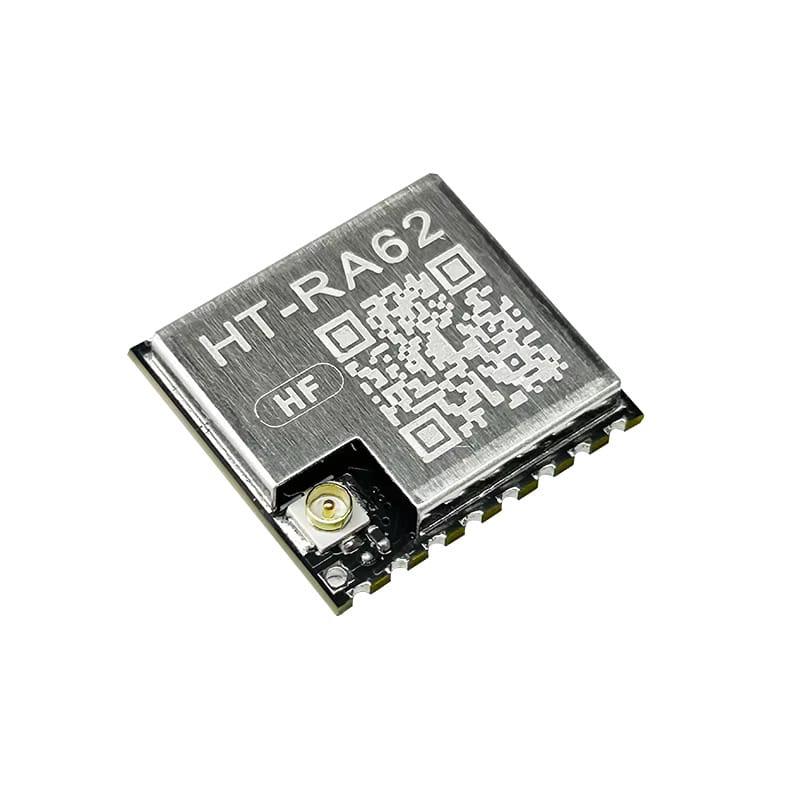
The HT-RA62 LoRa module is a compact, surface-mount (SMC) version of the popular LoRa radio, designed for integration into custom PCBs. Unlike the RA-02 DIP version, which features through-hole pins and is suitable for breadboarding and prototyping, the HT-RA62 requires more advanced soldering techniques and precise manual soldering. This trade-off, however, allows for a much slimmer and more space-efficient design.
The module supports both 433 MHz and 868/915 MHz frequency bands, depending on the specific model, offering flexibility for deployment across different regions in compliance with ISM band regulations. Built on the Semtech SX1262 newer chipset (typically the SX1276 or SX1278), it delivers high sensitivity and long-range communication capabilities.
Assembly
Since we're working with surface-mount components, this assembly will be more challenging than using through-hole components. Take your time and practice before starting if you're new to SMC soldering.
Step 1: Prepare the Pro Micro and PCB
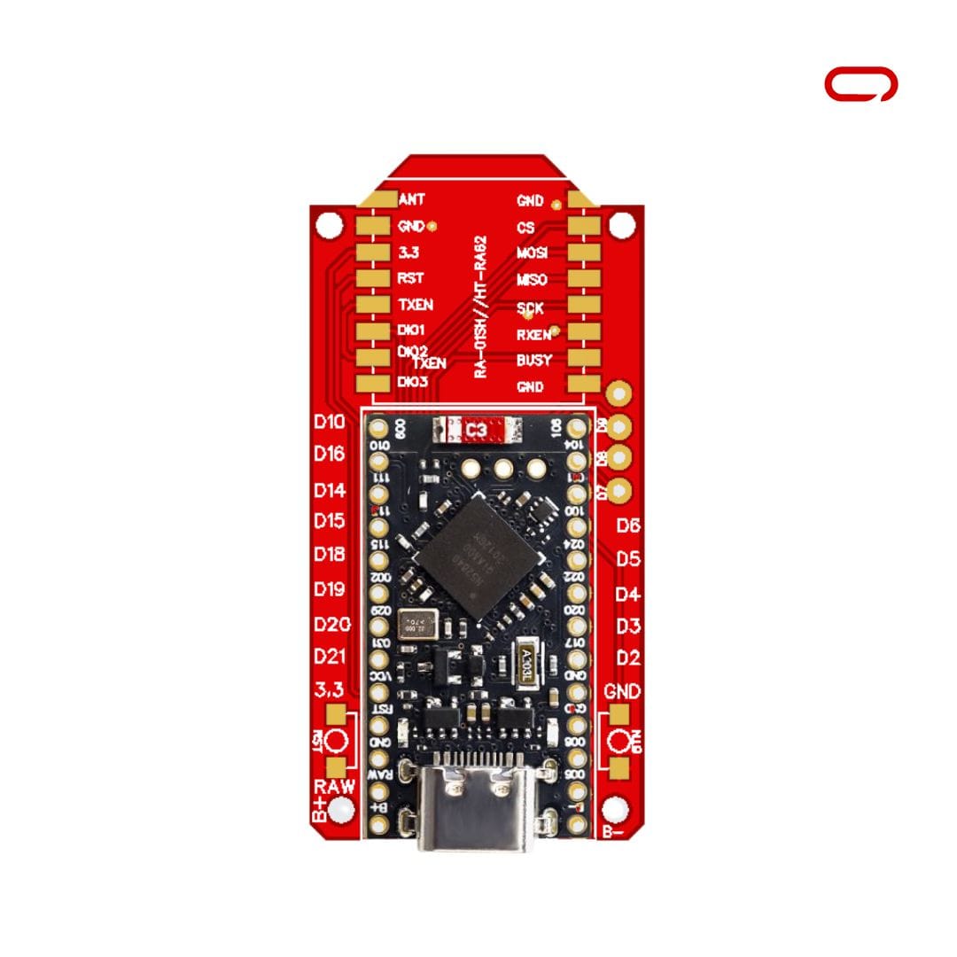
- Align the Pro Micro board with the holes on the PCB
- Ensure the USB port is facing outward, and the PCB is facing up
- You should see the Pro Micro on top with the PCB underneath, and above the Pro Micro, the two columns of 8 pads designated for the LoRa module
Step 2: Install and Solder the Pro Micro
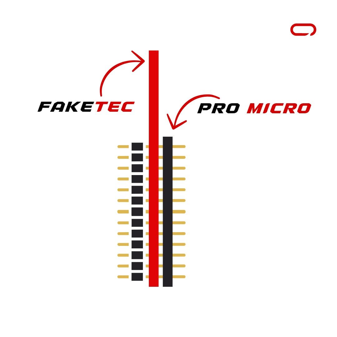
- Insert the header pins that came with the Pro Micro from the bottom of the PCB
- Push the pins through the PCB and then through the Pro Micro
- Place the entire assembly on a table with the pins pointing up
- Use tape to secure it in place if needed
- Begin soldering the pins
- Once all pins are soldered from the top, flip the board and break the black plastic holding the pins together using a small cutter (like those that come with 3D printers). Break it in chunks every 4 pins make a break. It will make it so much easier to remove it later on.
- Carefully peel away the plastic with the cutter tip
- Once all pins are soldered from the top and the plastic removed, solder from the bottom side for better conductivity
- Using wire cutters, trim the excess pins that stick out
- Cool down the Pro Micro first, then plug it into a power source to test if it still works
Step 3: Solder the LoRa Module
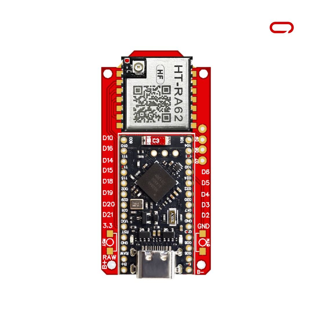
- Orient the LoRa module with the IPEX connector positioned at the top left corner
- Align it carefully with the pads on the PCB
- Since there are no pins to hold it in place, use electrical tape to secure it temporarily. Pro tip: Stretching the electrical tape makes it narrower, which can help secure the module to the board
- Begin by soldering one corner pad (GND or ANT is recommended)
- Once the first joint is complete, the module should be stable enough to continue soldering the remaining pads
- Take breaks as needed and work carefully - there's no rush!
Flashing The Software
Before using your Meshtastic node, you'll need to flash it with the appropriate firmware.
Step 1: Update the Bootloader
Most NRF52840 Pro Micro boards come with an outdated bootloader version that needs updating:
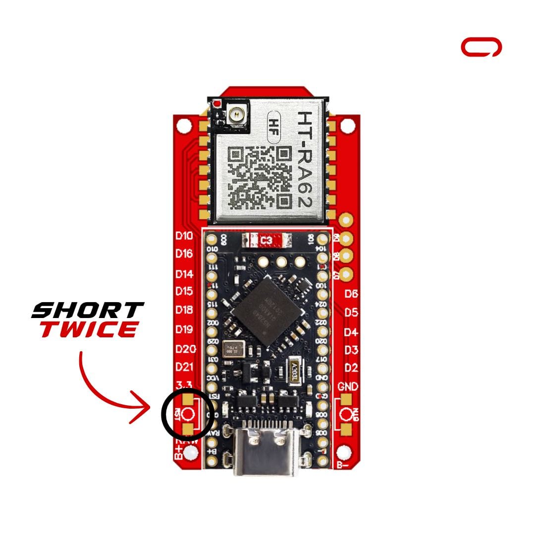
- Connect the node to your PC using a data cable
- Put the node into DFU (Device Firmware Update) mode by shorting the GND and Reset pins once or twice
- A new drive should appear on your computer
- Check the
INFO_UF2.TXTfile to determine your current bootloader version - Visit Adafruit's GitHub page for nRF52 Bootloader releases
- Find the next release after your current version (you must update incrementally)
- Download the
nice_nano_bootloader-X.X.X.HEXandnice_nano_bootloader-X.X.X.UF2files for your board - Drag and drop the
.HEXfile onto the drive first, then the.UF2file - The device will disconnect and restart
- Check the bootloader version again and repeat if necessary until you reach the latest version
Step 2: Install Meshtastic Firmware
- Visit the Meshtastic web flasher
- Select "NRF52 Pro-micro DIY variant" from the list
- Download the UF2 file
- Put your node in DFU mode again
- Drag and drop the downloaded UF2 file onto the drive
- Wait for the device to restart (this may take a minute or two)
Pairing Devices
With the hardware assembled and the firmware flashed, you're now ready to pair your FakeTec Meshtastic node with your phone:
- Download the Meshtastic app on your phone (available for both iOS and Android)
- Navigate to the Bluetooth page and wait for your device to appear
- Select your Meshtastic device from the list
- When prompted for a pairing PIN, enter "123456"
- Select your region based on your LoRa frequency (e.g., "EU433" for 433MHz modules)
- The node will restart, and you'll be ready to go!
Conclusion
Building your own Meshtastic node with the FakeTec PCB design offers an excellent balance of cost-effectiveness and functionality. At approximately $11 for the basic components, this DIY approach makes mesh networking accessible to hobbyists and enthusiasts.
The assembly process, while requiring some soldering skill, is straightforward when following the step-by-step instructions. The NRF52840 Pro Micro's integrated battery management and Bluetooth capabilities, combined with the compact HT-RA62 LoRa module, create a power-efficient node perfect for off-grid communication.