How To Add Screen To FakeTec NRF52840 Meshtastic Device
We'll walk you through adding a display module to your FakeTec Meshtastic Device to show messages, node information, and network status in real-time.
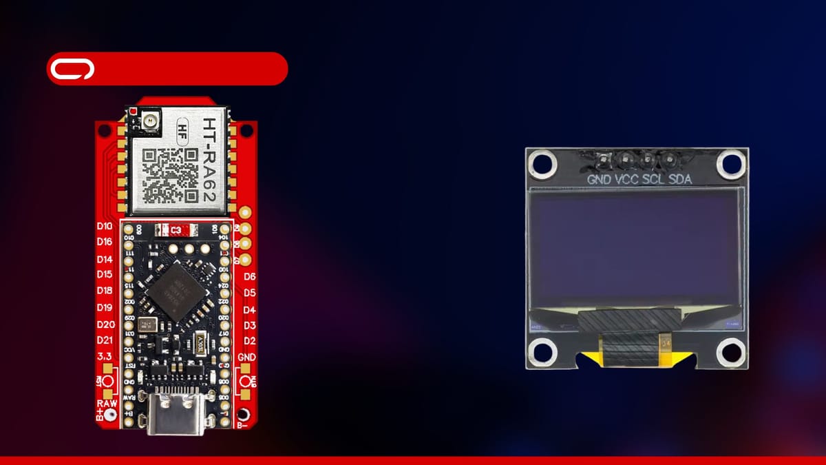
In this guide, we'll walk you through adding a display screen (OLED) module to your existing FakeTec Meshtastic Node to display messages, node status, network information, and navigation menus directly on your device.
Hardware
Now let's get started with the hardware you need:
- 1x BME280 Module - AliExpress Price: 2.00USD | Amazon US Price 6.99USD
- 4x Female to Female Pin Connector AliExpress Price: 0.42USD | Amazon US Price 5.49USD
- 1x Soldering Iron + 60/40 Solder Wire (Optional - You can go to a nearby electronic shop to solder the headers on the board)
While you can modify this hardware selection, we've chosen readily available components. Note that soldering is only required to attach headers to the FakeTec Node and the OLED display module. This step can be outsourced to a local electronics shop if you prefer to avoid soldering yourself.
Assembly
The hardware is all ready and set now to the wiring. For this, we will follow the following schematics.
OLED SSD1306 Display → FakeTec Meshtastic Node
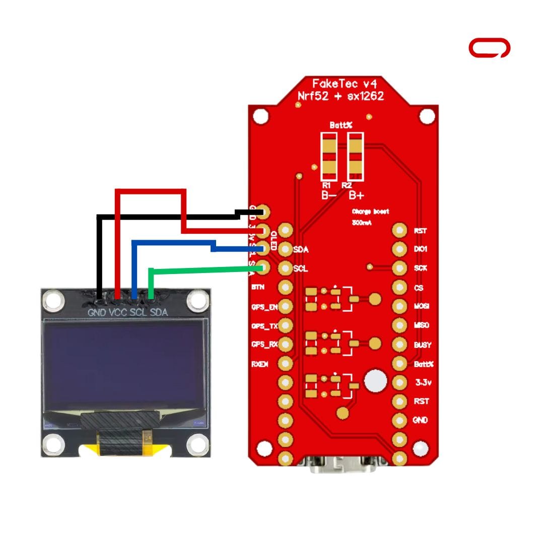
- VCC/VIN → 3.3V (OLED displays typically run on 3.3V)
- SCL → SCL Pin (I2C Clock)
- SDA → SDA Pin (I2C Data)
- GND → GND Pin
After completing all connections, verify that they match the recommended configuration before proceeding to the next stage.
Meshtastic Settings
- Open Meshtastic App (iOS/Android)
- Connect to your FakeTec device via Bluetooth
- Go to the Settings page
- Navigate to Device Config
- Select Display
- Configure the following settings:
- Screen On Interval: Set how long the screen stays on (e.g., 60 seconds)
- Auto Screen Carousel Interval: Time between automatic screen changes (e.g., 10 seconds)
- GPS Format: Choose coordinate display format
- Display Units: Select metric or imperial units
- OLED Type: Select SSD1306 (if available in options)
- Display Mode: Choose what information to show by default
- Additional Display Options:
- Flip Screen: Enable if your display is mounted upside down
- Wake on Tap: Enable screen activation on device movement (if supported)
- Heading Bold: Make compass heading more prominent
- Save Configuration and restart your device
Conclusion
Adding a display module to your FakeTec Meshtastic Node significantly enhances the user experience by providing real-time visual feedback without requiring a smartphone app. While some soldering may be required for header installation, this can be easily delegated to a local electronics shop if needed.